GL840 Series DATA LOGGER
Main | Features | Wireless LAN | Software | Specifications | Accessories | Support & Download
FEATURES
GL840 WITHSTAND-VOLTAGE MODEL
3-Types of input system enable for measuring various signals >>
Type 1: Multifunction analog input ports >>
Type 2: Support digital sensors >>
Type 3: Four-Channels of logic/pulse inputs >>
Maximum sampling interval of up to 10 ms >>
Built-in 4 GB flash memory with SD card support >>
3-INPUT SYSTEMS ENABLE TO MEASURE VARIOUS SIGNALS
Type 1: Multifunction universal analog input ports
Contains a highly isolated input channel system which ensures that signals are not corrupted by noise from other channels. GL840's inputs are suitable for combined measurements from voltage, temperature, humidity, logic, and pulse signals. Standard configuration has 20 analog input channels. Unit is expandable of up to 200 channels by adding optional 20 channel extension terminal base units (B-566) and input terminal blocks (B-564 or B-565).
| Withstand voltage & Accuracy | Multi-input type (GL840-M/B-564) | Withstand-voltage type (GL840-WV/B-565) | |
|---|---|---|---|
| Voltage | Input voltage range | 20 mV to 100 V | 20 mV to 100 V |
| Max. voltage (Input - GND) | 60 Vp-p | 300 Vp-p | |
| Temp. | Thermocouple | R, S, B, K, E, T, J, N, W (WRe5-26) | |
| RTD (Resistance Temp. Detector) | Pt100 (IEC751), Pt1000 (IEC751), JPt100 (JIS) | ||
| Accuracy | Voltage | ± 0.1% of F.S. | ± (0.05% of FS + 10μV) |
| Temperature* | ± 1.55 ºC | ± 1.1 ºC | |
* Accuracy rating for K-type thermocouple at 100˚C includes reference junction compensation. Accuracy varies by temperature levels and thermocouple types.
How a standard configuration is expanded to more than 40 channels (below)
Q: How do you configure the expansion blocks on the GL840 series?
There are several components that are required to set up the expansion terminal blocks for the GL840 models. Each model will require one expansion cable to connect the first expansion terminal base which would initially connect the first 20 channel block with the main instrument. The original 20 channel block from the main unit will snap out of the body, and the corresponding 20 channel block will then snap on to the first extension terminal base. This cable can now be either 1.6 ft (50cm) or 6.5 ft (2 meter) long. Thereafter, depending upon how many channels you will need to configure, each corresponding extension terminal base (B-566) will add additional 20 channel blocks either via a cable or directly daisy-chaining on to each other. Either the B-564 20 channel terminal block for the GL840-M or the B-565 20 channel terminal block for the withstand model GL840-WV can be used as the terminal block mixed together on the series of channel blocks.
Q: What are the key advantages for using the GL840-WV, and which applications do you recommend for the GL840-WV?
The key advantage of the GL840-WV model is in the precision accuracy of its measurement and its capability to withstand higher voltage requirements. Voltage accuracy on DC input is ±0.05% of full scale (+10µV), and average accuracy for thermocouple measurement increases by anywhere from 0.5˚C to 1.7˚C depending upon the range and the type of your typical thermocouple wires. (please review the specification below to review your specified range) The other key advantage is in its ability to withstand up to 300Vp-p channel-to-ground and 600Vp-p in between channels with 2300Vrms AC (for 1 minute) channel-to-ground. This provides the monitoring ability to connect series stacked cells for power batteries up to 300V with no issues as a viable monitoring tool for battery efficiency and performance. Solar panel networks and other power grid networks can now be monitored with this cost-efficient monitoring tool.
Configuration for additional channels
Number of channels |
20 channels |
40 channels |
100 channels |
200 channels |
|---|---|---|---|---|
GL840 unit (GL840-M or GL840-WV) |
1 set |
1 set |
1 set |
1 set |
Connection cable (B-567-05 or -20) |
N/A |
1 pc |
1 pc |
1 pc |
Terminal base (B-566) |
N/A |
2 sets |
5 sets | 10 sets |
Input terminal (B-564 or B-565 ) |
N/A |
1 set |
4 sets |
9 sets |
Offers longer cable for the input terminals
Input terminal blocks can be connected directly (in daisy chain), or using the B-567 cable(s). This allows the input terminals to be placed in separate locations according to the need of the application. The input terminal unit and the GL840 main body can be extended by using an extended connections cable.
* If the signal is affected by noise, it may be required to use a slower sampling.
Type 2: GS digital sensors
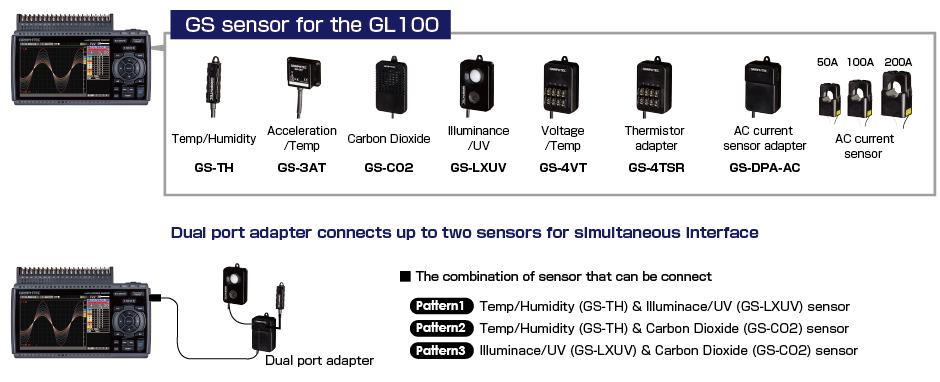
The GL840 multi-channel data logger allows users to switch sensors and terminals for measuring various signals. Digital sensors and input terminal/adapters for the GL100 connects to the GL840 directly. Available sensors/terminals to measure various signals with the GL840 data loggers are:
GL840 (configuration example) shown with dual port adapter (GS-DPA), CO2 sensor & illuminance/UV sensor
Type 3: Four-Channels of Logic/Pulse inputs
Supports 4-channels logic or pulse signal inputs. Pulse mode allows cumulative, instant, or rotational values for industrial measurement capability with speed and flow.
MAXIMUM SAMPLING INTERVAL OF UP TO 10 MS
Provides faster sampling rates for voltage measurements. Up to 10 ms sampling speed is achievable when limiting the number of channels in use.
Sampling Interval |
10ms | 20ms | 50ms | 100ms | 200ms | 500ms | 1s | 2s | |
|---|---|---|---|---|---|---|---|---|---|
Number of channel |
1 | 2 | 5 | 10 | 20 | 50 | 100 | 200 | |
Measuring |
Voltage |
● | ● | ● | ● | ● | ● | ● | ● |
Temperature |
- | - | - | ● | ● | ● | ● | ● | |
BUILT-IN 4 GB FLASH MEMORY WITH SD CARD SUPPORT
The new GL series enables reliable long term measurment with its built-in 4 GB flash memory and SD card slot for external storage devices. The SD card slot supports an SDHC memory card of up to 32 GB. The captured data can be stored in GBD (Graphtec binary data) or CSV file format.
Capturing time* (when all 20 analog channels are being used with Logic/Pulse inputs turned off.)
Sampling |
10ms | 50ms | 100ms | 200ms | 500ms | 1s | 10s |
|---|---|---|---|---|---|---|---|
GBD format |
31 days | 77 days | 95 days | 108 days | 270 days | Over 365 | Over 365 |
CSV format |
3 days | 11 days | 16 days | 21 days | 54 days | 109 days | Over 365 |
* Figures are approximate. File size of captured data is 2GB in GBD or CSV file format on this chart. Sampling interval is limited by the number of channels in use. (10ms:1ch, 50ms:5ch, 100ms:10ch). Limited sampling speed is available when digital sensors and GL100-WL are used as a remote monitoring device.
RING CAPTURE FUNCTION
The most recent data is saved when the memory is configured in ring memory mode. (Number of capturing data is 1000 to 2000000 points)
RELAY CAPTURE FUNCTION
Data is continuously saved to multiple files up to 2GB without losing any data until capturing is stopped when the memory is configured in the relay mode.
HOT-SWAPPING THE SD MEMORY CARD
SD card can be replaced during data capturing when the sampling interval is 100ms or slower.
USEFUL FUNCTIONS
Displays the data by a bar chart (in firmware ver.1.10 or later)
The integrated data that is measured by the digital sensors can be displayed by a bar chart in the GL840 series.
| Available GS sensors | Measurement | Unit |
|---|---|---|
| GS-TH (Temp/Humidity) sensor | Integrated temperature | ℃h |
| GS-DPA-AC adapter with GS-Acxxx sensor (AC current/power) | Integrated power | kWh |
| GS-LXUV (Illuminance/UV) sensor | Integrated illuminance | lxh or klxh |
| Integrated UV | mW/cm2h |
ALARM OUTPUT FUNCTION
Alarm signals can be placed using the four channel alarm output ports based on set conditions for each channel.
* Optional cable (B-513) is required.
USB DRIVE MODE
USB drive mode function enables data to be transferred to the PC from GL840 by drag & drop feature.
NAVIGATION FUNCTION
Simple to use navigation screen allows setting operation for measurement and wireless LAN adapter.
LARGE 7-INCH WIDE COLOR LCD
Monitoring data can be displayed in waveform or digital form. Parameter settings can be displayed on the screen.
3-TYPES OF POWER SOURCE
Choose from AC power supply, DC supply* or the rechargeable battery pack.*
* Optional accessories (B-514 or B-569) are required.
NETWORKING FEATURES
Various functions are available using a network.
Web & FTP server function, FTP client function, NTP client function
MATH FUNCTIONS FOR SCALING
Math Functions are available for scaled input from sensors and transducers with VDC scaled output or 4-20mA current loop.
FTP Client Function: Captured data is periodically transferred to the FTP server for backup.
NTP Client Function: The clock on the GL840 is periodically synchronized with the NTP server.
(The GL840 requires connection to a LAN environment using the Ehternet/WLAN ports for networking functions)
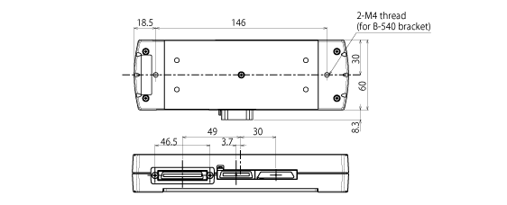
GL840-WV EXTERNAL DIMENSIONS
Scale: mmTolerance: +/- 3 mm
INPUT TERMINAL / BASE UNIT
■ Input terminal (B-564) with Base unit (B-566)
■ Input terminal (B-565) with Base unit (B-566)
■ Base unit for input terminal (B-566)
■ When two Base unit are connected.
Scale: mmTolerance: +/- 3 mm


