
GL7000 DATA PLATFORM
Main | Features | Modules | Software | Specification & Sizes | Accessories | Support & Download

GL7-DCO Analog Voltage Output Module
GL7-DCO Analog voltage output module simulates a recorded data form the GL7000 and outputs the source to the original equipment for mock simulation of anomalies and long term trend. The output signal can be in a simple waveform sampled at its original recorded intervals and can output a sine, pulse, ramp, triangle wave forms, or DC signals.

Analog voltage output from saved data on the main GL7000 reproduces anomalies and trend data from the recorded files
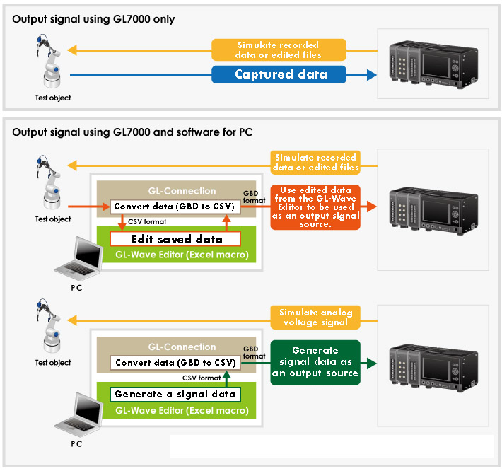
By reproducing recorded data, you are able to simulate the symptoms in real time.

The reference signal can be created using the GL-Wave Editor (Excel macro) software, you are able to output an analog voltage signal from this module
Saved data can be edited using the GL-Wave Editor which then can be used as a output signal for simulating the analog voltage out.
The GSD is an abbreviation for Graphtec Binary Data that is specified by Graphtec
The Software of the GL-Connection and GL-Wave Editor are standard accessory software for the GL7000 data platform
Simultaneously capture and output analog voltage from the GL7-DCO while recording data on other modules
By simulating abnormal signal conditions for the output of the recorded data, you can record and simultaneously measure the impact of the simulated data on the equipment being simulated by measuring strain, vibration, temp, and other conditions of the target test object.

Application examples

GL7-DCO specification
| Item | Description | |
|---|---|---|
| Type of module | Analog voltage output module | |
| Model number | GL7-DCO | |
| Number of output channels | 8 channels | |
| Output connector | SMA (Sub-miniature version A) connector | |
| Output method | All channels common ground, SMA (Sub-miniature version A) connector | |
| Sampling speed (interval) | Up to 100 k Samples/s (10 μs) | |
| Output condition | Source of data | Measurement data, Edited measurement data, Generated arbitrary data (*1), Generated simple waveform (DC voltage and sine, triangle, ramp, pulse waveform) |
| Source of measurement data | Module of Voltage (GL7-V), Voltage/Temperature (GL7-M), High speed voltage (GL7-HSV), High voltage (GL7-HV), DC strain (GL7-DCB), and Charge (GL7-CHA) | |
| Output condition | Signal can be measured by the input module even while the signal is output from the DCO module. Measurement data except the temperature, humidity and logic/pulse are able to output. | |
| Output range | Voltage | ± 1, 2, 5, 10 V Full Scale |
| Current | Up to ± 10 mA in each channel (total output current of unit is up to 40 mA.) | |
| Output impedance | Max. 1 Ω | |
| Output signal accuracy (*2) | ±0.25% of Full Scale | |
| D/A converter | Resolution 16 bits (effective resolution: 1/20000 of the output full range) | |
| Filter | Low pass | OFF, Line(1.5 Hz), 5, 50, 500, 5k, 50k Hz * This filter is the smoothing filter to remove the noise on output of the D/A converter. |
| External dimensions (W x D x H) | Approx. 49 x 136 x 160mm (Excluding projections) | |
| Weight | Approx. 770g | |
*1 CSV file must be created first to be used as the source for the arbitrary data using the GL-Wave Editor using EXCEL macro. Microsoft EXCEL 2003 (Office 2003) or later edition is required to be used with the GL-Wave Editor.
*2 Subject to the following conditions:
● Room temperature is 23ºC ±5ºC.
● When 30 minutes or more have elapsed after power has been turned on.