INSTRUMENTS > FAQ > TURNING ON THE PULSE LOGIC
TURNING ON THE PULSE/LOGIC INPUTS USING THE B-513 CABLE
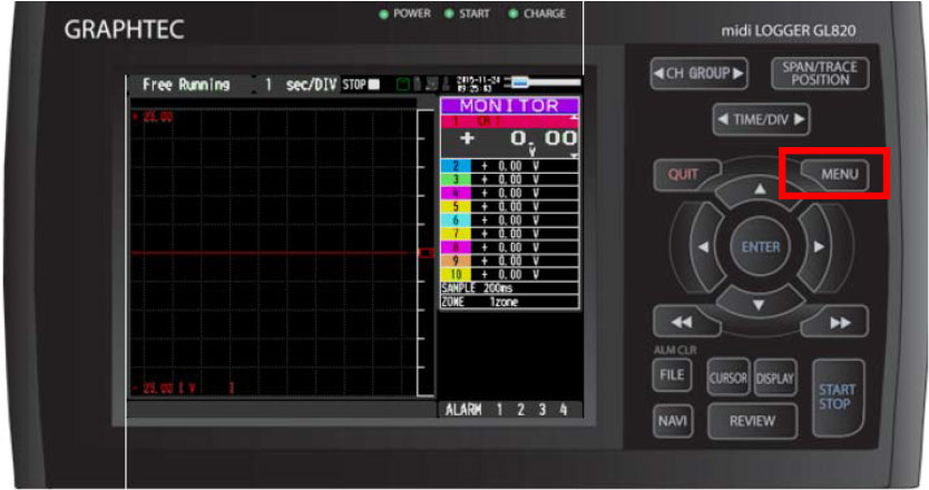
STEP 1: From the main screen on your unit, hit the “MENU” button to proceed the menu screen.
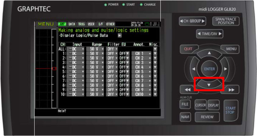
STEP 2: Once the “MENU” screen has come up, scroll down using the down arrow key.
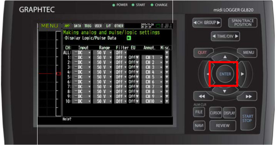
STEP 3: Scroll down once until you reach the “Display Logic/Pulse Data” and hit the “ENTER” Button.
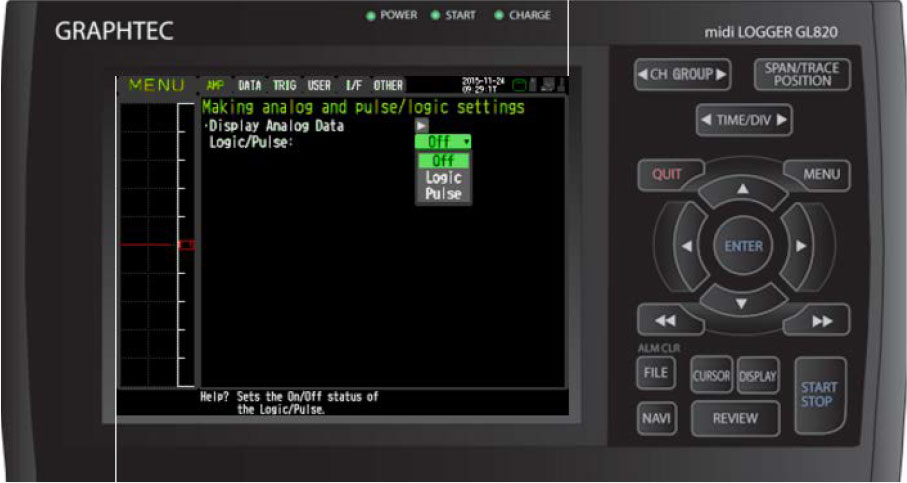
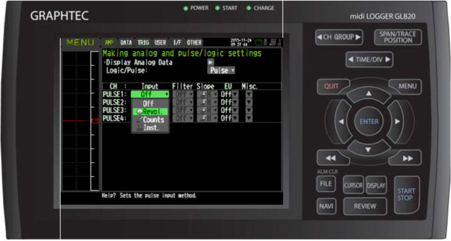
STEP 4: Once at the “making analog and pulse/logic settings” Menu, on the Logic/Pulse option, choose which one you would like to use. Either Pulse or Logic.
STEP 5: Now choose which Input you would like to use, you have 3 different options to choose from. "Revol." is for revolution measurement such as RPM. "Counts" is for accumulated counts for all pulse signals. "Inst." stands for instantaneous count for flow pulse totalization rate based on the chosen sampling rate.
<Calculation Formula for Revol.>
Number of revolutions (RPM) = Pulse input frequency ÷ Number of pulses per revolution x 60 (1 minute)
<Calculation Formula for "Inst.">
Counts the number of pulses for each sampling interval. Resets the count value after each sampling interval.
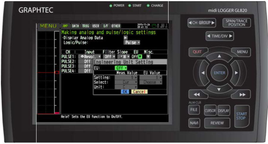
STEP 6: You can also use the Engineering scale to make sure the signal you have coming in is correct. When you are setting the highs and lows for your pulse/ logic signal, the first column which mentions the measured value will be your voltage range of the sensor that you are using. The second column, which is the EU (engineering unit) value will be the range at which your sensor can be read (ex: 0 – 60 PSI, 0 - 10 mph, 0 - 10 PPM, etc.).
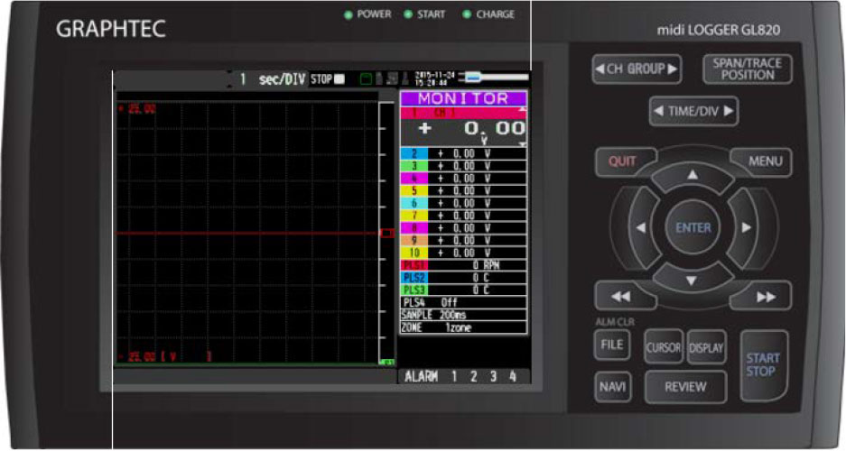
STEP 7: Once all of your values are set, you can hit QUIT on the GL to return to the main screen.
INSTRUMENTS > FAQ > TURNING ON THE PULSE LOGIC

