
INSTRUMENTS > FAQ > GL7000 > CONNECTION METHOD AND APPLICATION FOR STRAIN SENSOR
CONNECTION METHOD AND APPLICATION FOR STRAIN SENSOR

Data Platform GL7000 & Strain Unit GL7-DCB
GL7-DCB Strain Unit
CONNECTION AND APPLICATION:
Technical guide to measure with GL7-DCB
Data platform GL7000 strain unit
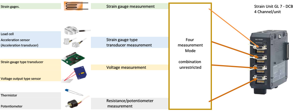
1) OUTLINE OF STRAIN UNIT (GL7-DCB)
The strain unit [GL 7 - DCB] is equipped with 4 channels of isolated input section per unit, each channel with strain gauge measurement,
Strain gage applied transducer, voltage measurement and resistance measurement with multi input type conditioner which can select for each channel.
- Built-in bridge capable of selecting 120 Ω / 350 Ω allows easy measurement with strain gauge.
- Bridge power supply supports constant voltage and constant current.
- Supports TEDS sensor.
- Low pass · anti aliasing filter installed.
- High precision measurement is available with remote sensing and shunt calibration function.
2) ABOUT THE CONFIGURATION AND ACCESSORIES OF THE STRAIN UNIT (GL7-DCB)


ACCESSORIES
For strain gauges and strain gage applied transducers NDIS terminals and DSUB connectors are used for connection with measuring instruments.
For the strain unit [GL 7 - DCB], connectors and conversion cables corresponding to them are prepared.

3) DIP SWITCH SETTING OF STRAIN UNIT (GL7-DCB)

IN THE CASE OF STRAIN GAUGE INPUT:
For strain input, set the bridge circuit with the DIP switch. Always set according to the strain gage resistance.
IN THE CASE OF STRAIN SENSOR INPUT:
(strain sensor: strain type converter (strain gauge type acceleration sensor, load cell, etc.)) In the case of the strain sensor input, the setting differs depending on whether the sensor is 4-wire type or 6-wire type.

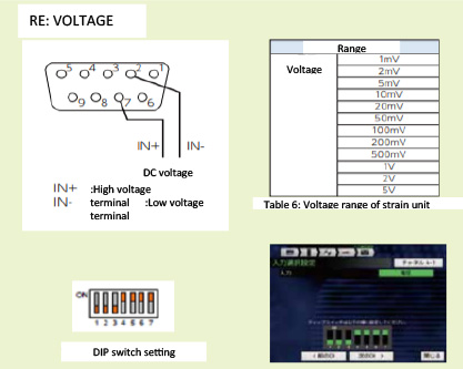
IN CASE OF VOLTAGE INPUT / RESISTANCE INPUT:
In case of voltage input or resistance input, make the setting shown as below regardless of distortion force.

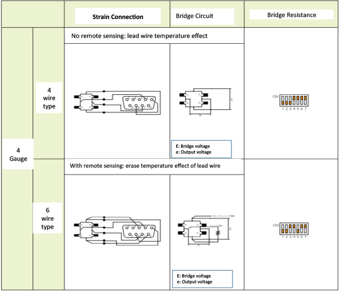
4) ABOUT STRAIN GAUGE AND BRIDGE CIRCUIT CONFIGURATION
Table 3: Strain connection and bridge circuit, 1-guage


Table 3: Strain connection and bridge circuit, 1-guage

Table 3: Strain connection and bridge circuit, 2-guage

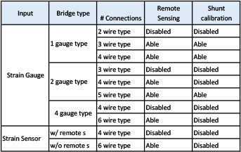
5) ABOUT SETTING METHOD OF STRAIN GAUGE AND STRAIN SENSOR
STRAIN GAUGE: Please refer to [Table 1: Connector number and contents], [Table 3: Strain connection and bridge circuts] to connect the strain gage and the input terminal wiring of the unit.

ON SELECTION SCREEN, CHOOSE [STRAIN GAUGE]
strain gage and the input terminal wiring of the unit.
- Select the bridge type from 1, 2, 4 gauge.
- Select the number of connections. Since the content of the number of connections varies depending on the bridge form,
- Please choose from the contents
- For 1 gauge · 2 gauge, select either 120 Ω or 350 Ω gauge resistance to be used.
- In the case of 4 gauge, input the gauge resistance numerically.
- Return to the input screen and select bridge voltage from the selection of other[setting] sensor setting.
Set the displayed DIP switch setting to the unit's dip switch.

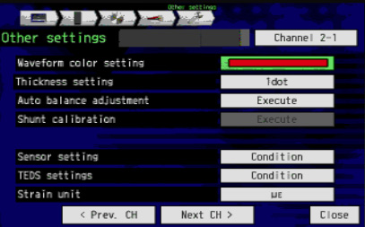
Please set measurement ranges, filters, scaling etc. on the input setting screen. Prior to measurment taking, do auto balance adjustment at other [setting] of the input screen, or press the auto balance switch at the top of the unit and set the initial value to zero.
Supplement: Shunt calibration function to correct error of strain gauge at other [setting] of input setting. There is a remote sensing function that corrects the resistance of the lead wire. (Reference: 8 shunt calibration, remote sensing)
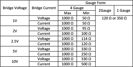
Table 4: Resistance values that can be input by setting the bridge voltage
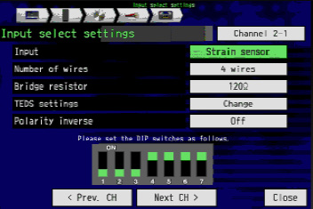
STRAIN SENSOR: (when using a strain type converter (strain gauge type acceleration sensor, load cell, etc.))
Please refer to [Table 1: Connector Number and Contents] and [Table 3: Strain Connection and Bridge Circuit] for connection wiring of the strain sensor and unit input terminal
- Select from strain sensor number of 4 wire or 6 wire connection.
4 wire: without remote sensing function Sensor
6 wire: sensor with remote sensing function
- Enter the bridge resistance value of the strain sensor numerically
- Return to the input setting and select bridge voltage from other sensor setting.
- Enter the numeric rated output of strain sensor in the other [Setting] of input setting picture. The unit is μV / V.
- Enter the calibration coefficient of the strain sensor to be used in numeric value.
- Select the unit according to the type of strain sensor.
- Set measurement ranges, filters, scaling etc. on the input setting screen.

Please set the displayed DIP switches with the DIP switch of the unit
- Set measurement ranges, filters, scaling etc. on the input setting screen.
- Prior to measurement taking, do auto balance adjustment at the other [setting] of the input screen or press the auto balance switch to set the initial value to zero.
- Supplement: for a sensor with TEDS function, there is a function to automatically read stored information, rated capacity, rated output and unit (Reference: About TEDS)

Table 5: Resistance value that can be input by setting bridge voltage
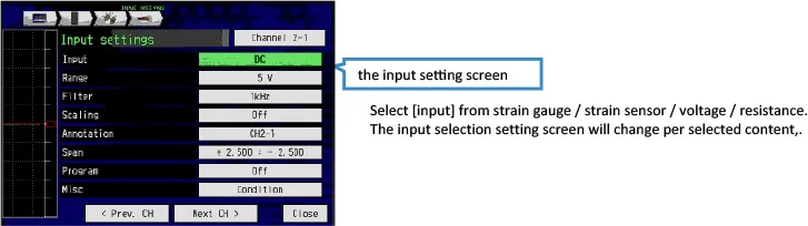
6) CONNECTION METHOD AND SETTING FOR RESISTANCE AND VOLTAGE MEASUREMENT

INPUT SETTING SCREEN
Select strain gauge / strain sensor / voltage / resistance input select input. The input selection setting screen changes depending on the selected content.

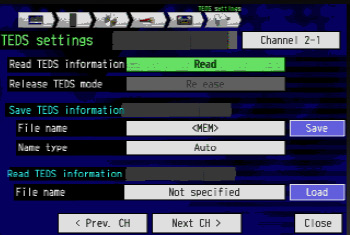
7) ABOUT TEDS
When TEDS compatible sensor is used, rated capacity, rated output and unit stored are automatically loaded into the instrument.
The TEDS function corresponds to the IEEE 1451.4 standard template No. 33 (strain sensor).
- Read TEDS information acquisition with the TEDS setting on the screen. Determined settings for various unit of strain sensor
- Set range change, filter or scaling according to the measurement condition obtained above.
- Set the DIP switch same as the DIP setting displayed at the bottom of the input selection.
~Connection setting is complete~
8) ABOUT SHUNT CALIBRATION AND REMOTE SENSING
The shunt calibration function: Corrects the error of the strain gauge.
The built-in shunt resistor (about 60 kΩ: when about 120 Ω · about 175 kΩ: 350 Ω) and the strain gauge to be used are internally connected In parallel to automatically correct (calibrating) errors to minimize the measurement range for higher accuracy performance.
Remote sensing function: Correct the resistance of the lead wire.
The remote sensing function eliminates an error factor of conductor resistance change of the cable. When wiring to the remote sensing terminal by connecting each strain gauge measuring method of 1 gauge method, 2 gauge method gauge method or strain type transducer sensor, it supplies a stable voltage excluding the voltage drop due to the conductor resistance of the cable to the object to be measured.
Shunt Calibration Setting:
Start Shunt Calibration by Selecting Execute:
9) FOR ACCURATE MEASUREMENT
The following methods are available to improve measurement accuracy for strain gage and strain gauge type conversion sensor.
1) Gauge factor correction
For the strain gauge measurement of GL 7 - DCB (strain unit), the strain is calculated with a gauge factor of 2.0. If the gauge factor of the strain gauge used for the measurement is different from 2.0, the true strain is obtained by the following equation.

2) Measurement method corresponding to environmental temperature change
2.1. In addition to distortion caused by external force, distortion occurs due to the temperature changes. By using a self-temperature compensating gauge that corrects the coefficient of linear expansion of the object to be measured, it can eliminate the influence of apparent distortion due to the difference in coefficient of linear thermal expansion.
2.2. When the wiring cable is long or the temperature of the measurement environment is extreme, the change in conductor resistance of the cable is measured as the strain change by appearance.
2.2.1. Remote sensing function (Utilization of remote sensing terminal)
Remote sensing function eliminates conductor resistance change of cable which is an error factor. When each strain gauge measurement method of 1 gauge method, 2 gauge method, 4 gauge method or strain type transducer sensor is connected to the remote sensing terminal, it provide a stable voltage that eliminates the voltage drop due to the conductor resistance of the cable to the object to be measured.
2.2.2. Utilization of constant current drive
When it is difficult to add cable wiring and sensor remediation function can not be utilized with strain transducer sensor measurement, select the constant current drive method. In the constant current drive of the tester, convert the sensor bridge circuit input resistance R of the strain type to a numerical value, then select the excitation voltage E of the bridge circuit from 1, 2, 2.5, 5, 10 V. Once selected, it controls the constant current that generates stabilization voltage that satisfies the following formula.

Hence, when constant current drive is selected, the voltage drop due to the conductor resistance of the wiring cable is eliminated, and a stable voltage is supplied to the strain type conversion sensor.