
INSTRUMENTS > FAQ > GL7000 > CONNECTION METHOD AND APPLICATION FOR ACCELERATION SENSOR
TIPS AND INFORMATION ON ACCELERATION UNIT GL7-CHA FOR DATA PLATFORM GL7000

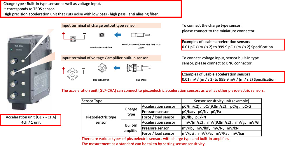
Data Platform GL7000 Acceleration Unit GL7-CHA
1) OUTLINE OF ACCELERATION UNIT (GL7-CHA)
The acceleration unit [GL 7 - CHA] has 4 isolated input sections in one unit. Each input channel is a multi-input type signal conditioner that can select charge type sensor measurement, built-in amplifier sensor measurement, and voltage measurement for each channel.
2) SETTING METHOD OF ACCELERATION UNIT (GL7-CHA) WITH DISPLAY UNIT INSTALLED FOR BUILT-IN AMPLIFIER
Please choose built-in amplifier type on the setting screen. Select [Input] from Charge type / Built-in amplifier type / DC / AC / Charge type - RMS / Built-in amplifier type - RMS / DC - RMS / AC - RMS.

The input selection setting screen changes depending on the selected content.


Sensor with built-in amplifier:
- Set to Input amplifier built-in type or built-in amplifier-RMS.
- Select other [Setting] item according to the sensor specifications.
- Set the sensor sensitivity to numerical value input.
- Select the applied current. 4 mA / 8 mA
- Set the range.
- Refer to [Table 1: Range and voltage sensitivity setting content].
The selection of voltage sensitivity and range changes.

As this is an acceleration sensor, set the processing contents with "Scaling integral setting" when processing speed or displacement, .
The acceleration sensor can be set with the above setting, please set the measurement range, filter etc.
※ The above is the unit notation of the acceleration sensor. For other sensors please replace the unit.

3) ABOUT TEDS

When using a TEDS compatible sensor, the stored information as the rated capacity, rated output and unit are automatically loaded into the acceleration unit [GL 7 - CHA]. The TEDS function corresponds to the IEEE 1451.4 standard template No. 25 (acceleration sensor).
※ Other than acceleration sensor is not supported.
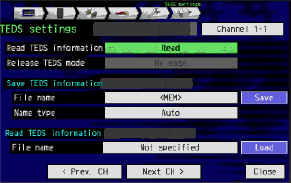
- "Please read" TEDS information acquisition with the TEDS setting on the screen.
- Please set range change, filter and scaling according to the measurement condition after reading above.
- Connection setting is completed.
4) ACCELERATION TO SPEE CONVERSION

Acceleration is converted to speed by time integration of acceleration. The relationship between acceleration and speed is explained using the trigonometric function Sin that can express vibration most simply.
When oscillating with amplitude A and angular acceleration ω, the following expression is satisfied.

① If you time integrate the equation, it becomes the speed and the speed is expressed by the formula ②.
Since angular acceleration ω is replaced with ω = 2π · f (f: frequency),
equation ② becomes the formula ③.
When converting an acceleration signal oscillating at an angular acceleration ω into a speed. The amplitude of the signal converted to the velocity with respect to the amplitude of the acceleration is inversely proportional to the frequency.
When converting an acceleration signal oscillating at an angular acceleration ω into a speed. The amplitude of the signal converted to the velocity with respect to the amplitude of the acceleration is inversely proportional to the frequency.
The speed conversion function of GL 7000
For the speed conversion function of the GL 7000, it is recommended to convert the speed signal of the acceleration signal with the frequency component of 10 Hz to 200 Hz. With frequencies above 200 Hz, the speed converted amplitude will be small and the measurement error will be large.
Note 1): When converting the acceleration to the speed, set the acceleration range as small as possible within the range not to over-scale the acceleration range of the measurement.
Note 2): When converting an acceleration signal with constant amplitude into a velocity signal regardless of frequency, the amplitude of the velocity signal is inversely proportional to f (f: frequency). When converting an acceleration signal of 200 Hz into a speed compared to the case of converting an acceleration signal with a frequency of 10 Hz to a velocity, the amplitude of the velocity signal is one-twentieth. In the speed conversion of the GL 7000, the recommended range is from 10 Hz to 200 Hz.
Note 3): In the GL 7000, the unit of acceleration is m / s 2, and the unit of speed is mm / s.
Note 4): As the speed conversion function of the GL 7000 is converted to speed by the integrating circuit, it cannot
be converted from the data after recording
5) DISPLACEMENT TRANSFORMATION FROM ACCELERATION
Acceleration is converted to speed by time integration of acceleration. Further integration of speed with time will result in displacement. As the speed conversion, the relationship between acceleration and displacement is explained by using trigonometric function Sin which express vibration in simple manner.

① If you time integrate the equation, it becomes the speed and the speed is expressed by the formula ②.
② When the equation is time-integrated, it becomes the displacement, and the displacement is expressed by ③ formula.
Since angular acceleration ω is replaced with ω = 2π · f (f: frequency), equation ③ becomes the following formula ④.
Hence -1 ≤ Sin (2 π · f · t) ≤ 1, the displacement amplitude will be inversely proportional to the square of 2π · f (f: frequency).
When converting the acceleration signal oscillating at angular acceleration ω into displacement, the amplitude of the signal converted to the displacement with respect to the amplitude of the acceleration is inversely proportional to the square of 2π · f (f: frequency).
About displacement function of GL 7000
For the displacement conversion function of the GL 7000, signals with frequency components from 10 Hz to 70 Hz. is recommended. At frequencies above 70 Hz, the speed converted amplitude is small and the measurement error increases.
Note 1): When converting acceleration into displacement, set the range as small as possible not to over scale the range of measurement.
Note 2): When converting an acceleration signal with constant amplitude into a displacement signal regardless of frequency, the displacement amplitude is inversely proportional to the square of 2π · f (f: frequency) In the case of displacement transformation of the acceleration signal of 70 Hz, the amplitude of the displacement signal is about 1 / 50th as compared with the displacement conversion of the acceleration signal of frequency 10 Hz. For the displacement conversion of the GL 7000, the recommended frequency range of the acceleration signal is from 10 Hz to 70 Hz.
Note 3): In the GL 7000, the unit of acceleration is expressed in m / s 2, and the unit of displacement is expressed in mm. In case
Note 4): Since the displacement conversion function of the GL 7000 is converted to displacement by the integrating circuit, it can not be converted from the data after recording.