SOFTWARE > GRAPHTEC PRO STUDIO PLUS
EZ CUSTOMIZED VARIABLE DATA AND IMAGES
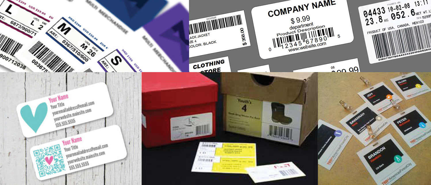
Using Graphtec Pro Studio Plus allows you to easily create coded patterns, such as a bar-code, QR code, or data matrix code, and printing objects having variable data.
Now brands are taking personalization a big step forward into mass customization. They are discovering that they can elevate customer loyalty and engagement - and use their customer base as an engine of advocacy to potential buyers. Product customization helps brands boost sales on their own websites or gain share on a retailer’s site.
Direct maila
Material tracking
Product tracking
Event marketing
Trade show marketing
Serial numbered labels
Asset tag and labels
Tickets
Barcode labels and tags
Serialized membership cards
Scratch off game pieces
Security and tamper evident labels
Customized QR codea
Parking permit labels
Variable Information on roll sheet medias
MAIN FEATURES
PERSONALIZATION CHANGES ANY ELEMENT & INCREASE VALUE
COMBINE ART WORKS WITH VARIABLE DATA
It is able to easily create coded patterns, such as a bar-code, QR code, or data matrix code, and printing objects having variable data.
VARIABLE: BAR CODES
VARIABLE: NAMES / ADDRESSES / PRICES / NUMBERS
VARIABLE: QR CODES
PIXELATE IMAGE TO SHARP IMAGE
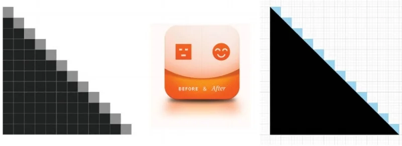
Graphtec Pro Studio Plus has smart tool to detect and able to process the bitmap image by applying a filter for removing dot noise or controlling sharpness.
REDUCE NOISE - erasing the dot noise such as in scanned images.
BLUR - blurring the image by taking the average of the pixels around the pixel.
SHARPEN - making the sharpen image by increase the contrast between pixels.
There is also available filters such as the level to change the amount of color to use. Color balance to increase or decrease specific color. Brightness / Contrast to adjust brightness, saturation, and contrast.
1-CLICK VECTOR PATH
There is more a special tracing function to vectoring the bitmap image in the Graphtec Pro Studio Plus.
COLOR TRACING - Graphtec Pro Studio Plus generates vector data for each color used from color bitmap images. It is able to create cut data for each color of the bitmap image, and then different cutting conditions can be assigned for each color.
DOUBLE YOUR PRODUCTIVITY WITH POWER NEST
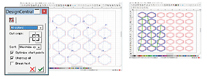
A object is able to be efficiently pleased on media using power nest (nesting) function. It enables to reduce a cost of media by less waste and also reduce processing time of cutter.
A object is able to be efficiently pleased on media using power nest (nesting) function. It enables to reduce a cost of media by less waste and also reduce processing time of cutter.
DOUBLE PRODUCTIVITY FROM 3 TO 6
DOUBLE PRODUCTIVITY FROM 8 TO 16
CUTTING PREVIEW IN ANIMATION
It is displayed the order of cutting by animation. The cutting order of objects can be set automatically or manually. It enables to improve productivity by reducing the cutting process time and to prevent problems in the cutting process by previewing the cutting order of object.
CUTTING SIMULATION (CHANGING CUTTING ORDER)
It is displayed the order of cutting by animation. The cutting order of objects can be set automatically or manually. It enables to improve productivity by reducing the cutting process time and to prevent problems in the cutting process by previewing the cutting order of object.
It is required to review the following license agreement before the software is downloaded.
MAIN FUNCTIONS
| Category | Function | GPS | GPS+ | Description |
|---|---|---|---|---|
| Price | Included with Cutter | X | - | Graphic Pro Studio Plus must be purchased separately |
| File | Acquire Image | X | X | Capturing the image from the scanner. |
| Archive to Cloud | X | X | Saving the job to the SAiCloud. | |
| Send to Approval Tool | X | X | Saving the job to the approval tool on the SAiCloud. | |
| Work-space | X | X | Switching the location of the menus and buttons like the style of the software that is familiar with you. | |
| View | Color | X | X | Editing the color. |
| Show | X | X | Displaying the ruler, grid and guide lines. | |
| Snap | X | X | Moving the object relative to the guide or grid. | |
| Arrange | Group | X | X | Grouping objects. |
| Lock | X | X | Locking the object for setting to non editable. | |
| Contour Cut | X | X | Creating a contour cutting line of objects. | |
| Convert to Outlines | X | X | Converting the object to path. | |
| Path Direction | X | X | Specifying the direction of cutting when the object data is output. | |
| Order | X | X | Arrange the selected object as bring to the front or send to the back. | |
| Align | X | X | Aligning the object to reference that is specified in sub-menu. | |
| Distribute | X | X | Distributing all objects evenly in the effective area by the specified method. | |
| Nest | - | X | Performing the simple nesting by moving the object along the X- or Y-axis. | |
| True Shape Nest | - | X | Performing the advanced nesting by moving the object including the rotation. | |
| Deskew | - | X | Correcting a skew of the imported image from the scanner. | |
| Step and Repeat | X | X | Performing complex replication as the matrix copy. | |
| Auto Serialize | - | X | Creating a copy of the object that has the serialized number in each copy. | |
| Cut Order | - | X | Starting the cutting simulator that shows the cutting order in the animation. | |
| Text | Font | X | X | Setting the font type of the character. |
| Justification | X | X | Aligning the string of text. | |
| Find/Replace | X | X | Search or replacing the text. | |
| Check Spelling | - | X | Checking the spelling. | |
| Case | X | X | Switching between uppercase and lowercase in letters. | |
| Insert Symbols | - | X | Creating the Braille, bar code, QR code, and data matrix. | |
| Effects | Combine | X | X | Combining objects. |
| Lens | - | X | Changing the appearance by applying a lens effect to overlapped objects. | |
| Contour Cut | X | X | Creating the cutting line of objects. | |
| Contour Cut Mark | X | X | Creating the registration marks to the object that has the cutting line. | |
| Page Contour Cut Mark | X | X | Cutting the object that is located the outside area enclosed by the registration marks. | |
| Distortion | - | X | Deforming the object. | |
| Shadow | X(*) | X | Adding shadows to objects. (* Only drop shadow.) | |
| Color Trapping | - | X | Removing the overlapping portions of objects without a gap | |
| Brend | - | X | Creating new objects that is changing the shape and color in stepwise between the specified two objects. | |
| Rhinestone Fill | - | X | Creating holes for the rhinestone that fills the object or fits the contour of the object. | |
| Bitmap | Bitmap Edit Toolbar | X | X | Editing a bitmap object. |
| Vectorize (Auto-trace) | X | X | Automatically converting the bitmap object to the path. | |
| Vectorize (Others) | - | X | Converting the bitmap object to the path. | |
| Rasterize | - | X | Converting a vector object into a bitmap. | |
| Filters | X | X | Applying filter effect to the bitmap object. | |
| Tools | Vector Eraser | X | X | Clearing any objects in the area that specify by dragging of the eraser tool. |
| Cleaver by Path | - | X | Splitting the created object, each split object can be edited. | |
| Cut/Plot | Preview window | X | X | Moving the tool carriage that response to the position change of the cutting job. |
| Preview | X | X | Showing the actually cutting job size by moving the tool carriage. | |
| Copies | X | X | Specifying the number of copies of the job. | |
| Repeat job | X | X | Specifying to send the job to the cutter repeatedly. | |
| Centering | X | X | Specifying location of the job on the page. | |
| Rotate | X | X | Rotating the job in 90 degree. | |
| Mirror | X | X | Creating the mirror image of the job. | |
| Total tiles | X | X | Displaying the total number of tiles. (Indication only) | |
| Weed lines | X | X | Adding lines for weeding. | |
| Weed border | X | X | Adding the border line in the specified margin for weeding. | |
| Driver option | X (*) | X | Enabling to specify the cutting condition for each color / layer. (*Color only) | |
| Change order of color or layer | X (*) | X | Specifying the cutting order for each color / layer. (* color only) | |
| Pause between colors or layers | X (*) | X | Pausing after the end of cutting of each color / layer. (* Color only) | |
| Import or export the cutting condition settings | X | X | Saving or loading the cutting conditions. | |
| Over cut | X | X | Cutting the contour line longer by the specified length in order to completely cut objects. | |
| Eliminate line-segment overlap | X | X | Deleting the overlapped paths or others. | |
| Position offset | X | X | Moving the cutting job in specified distance. | |
| Offset in registration mark | X | X | Adjusting the cutting position within the area enclosing the registration marks. | |
| Divide (cut segment) | X | X | Performing the process for each segmented area when there are additional registration marks on the cutting job. | |
| Revers-side Registration Mark | X | X | Making process at the reverse-side using the registration marks printed on the front surface. | |
| Save to file | X | X | Creating the plot file for offline operation. | |
| Use Bar-code | X | X | Creating the bar-code for managing the cutting data. | |
| Reversed color mark | X | X | Creating the registration marks in reversal color that is the white mark on black background. |
(*) X : Available
SUPPORTED FILE FORMAT FOR IMPORT
| File format | Extension | File format | Extension |
|---|---|---|---|
| D-CUT Master (* Graphtec Pro Studio only.) | CUT | EnRoute | ENR |
| Portable Document Format | Flexi SIGN 5.x | fs, pd, fd, fc, fe | |
| Adobe Illustrator | AI | Flexi SIGN 6.x, 7, 7.5 | FS |
| Encapsulated Postscript | EPS | Gerber Clip Art | GCA |
| Auto CAD Interchange Format | DXF | HPGL | hpg, hgl, plt |
| CorelDRAW Exchange Meta-file | CMX | HPHL / 2 | hpg, hgl, plt |
| Windows Meta-file | WMF | Ikuras | IK |
| Portable Network Graphics | PNG | Inspire | SCI |
| Joint Photographic Experts Group | JPEG | JPEG | JPG |
| Bitmap | BMP | Kodak Flash-pix | FPX |
| Tagged Image File Format | TIFF | Kodak Photo-CD | PCD |
| Personal Computer Exchange | PCX | Macintosh Quick-draw PICT | PCT |
| AutoCAD Drawing | DWG | Targa | TGA |
| CASmate | SCV | Text File | TXT |
| Clip Art | CA | Zsoft PC Paintbrush | PCX |
| Digital Microprocessor Plotter Language | PLT |
(*1) Restricted items in using SVG file
• When the SVG file containing registration marks is imported for print and cut application, it is required to specify or add contour cutting line.
• When editing contents in the imported SVG file, it is required to ungroup contents.
• Font size of text included in the SVG file are not reproduced. It is recommended that converting the font to outline before creating the SVG file.
• Following elements contained in the SVG file may not be reproduced correctly.
Gradation, Transparent, Pattern, Image, Layer
• The SVG files created under the following conditions can not be used.
- When registration marks are contained in the SVG file, the SVG file is created by an application that is different from the application created the register marks.
- The SVG file is created by the Export function. It is required to create the SVG file using Save As on File menu.
(*2) Restricted items in using file created by ROBO Master (file type: GSD, GST, GSP)
• When the ROBO Master file containing registration marks is imported for print and cut application, it is required to specify or add contour cutting line.
• When editing contents in the imported ROBO Master file, it is required to ungroup contents.
• When opening a ROBO Master file containing text, a screen for selecting fonts is displayed, it is required to specify the font to use. The imported text is handled in the same way as the text written in Graphtec Pro Studio, the outline may not match the display on the ROBO Master even if the same font is specified. It is recommended to convert the text to outline data in advance using the Join graphic menu on Edit menu of ROBO Master.
• Following elements contained in the ROBO Master file may not be reproduced correctly.
Gradation, Transparent, Pattern, Image, Layer, Font.
SYSTEM REQUIREMENTS
| Item | Description |
|---|---|
| Supported cutting plotter | CE7000 series / FC9000 series / CE LITE-50 / CE6000 Plus series / FC8600 series / CE6000 series FCX4000 series / FCX2000 series / FC4500 series / FC2250 series |
| Supported OS | Windows 10 / 8.1 / 8 / 7 |
V 3.40 (Lastest Version)
| Date of updated | 29 Sep, 2017 | ||
| Supported Products(*2) | CE7000 series / FC9000 series / CE LITE-50 / CE6000 Plus series / FC8600 series / CE6000 series | ||
| Supported OS(*1) | Windows 10 / Windows 10 64-bit edition | Home / Pro / Enterprise / Education | |
| Windows 8.1 / Windows 8.1 64-bit edition | Windows 8.1 / Pro / Enterprise | ||
| Windows 8 / Windows 8 64-bit edition | Windows 8 / Pro / Enterprise | ||
| Windows 7 / Windows 7 64-bit edition | Ultimate / Enterprise / Professional / Home Premium / Home Basic | ||
| System requirements | Processor | Intel Core i3 or higher | |
| RAM | 8GB or more | ||
| Install space needed | 10GB or more | ||
| Video | 1152 × 854 (at least), 16 bit color or more | ||
Revision History
Ver.3.40
Update: 26 May, 2021
Fixed the problem that the designed is not displayed when opening PDF file with images output by Graphtec Studio.
Ver.3.30
Update: 16 Dec, 2020
Enabled to open 64bitJOB file saved with CM4-Mac.
Ver.3.20
Update: 2 Dec, 2020
Made it unable to send another data from PC while FC9000/CE7000 is cutting a data with network connection.
Fixed the problem that the sensor does not recognize the second registration mark when [Detect the four registration marks for first adjustment] is selected in Matrix copy mode.
Ver.3.10
Update: 5 Aug, 2020
Fixed the problem that a time out error may cause when operating continuous cut with Data Link Server. (FC9000 / CE7000)
Enabled XPF output of JOB files saved to the "Production Manager". (FC9000 / CE7000 / FCX4000 / FCX2000 / CE LITE-50)
Ver.3.00
Update: 24 Jun, 2020
Added a choice of Long Barcode in [Registration Marks] > [Barcode Length] menu.
Changed the default setting of [Registration Marks] > [Barcode Length] menu from "Normal (0.4mm)" to "Long (0.8mm)".
Added a warning message to pop out when selecting a wrong port in connecting the plotter via TCP/IP.
Added a warning message to pop out when selecting a wrong port in [Change Port] menu.
Fixed the problem that maximum number of copies on horizontal direction cannot be specified when using data with cut lines outside registration marks.
Fixed the problem that registration marks on second copy or later do not be displayed correctly when copying the work to horizontal/vertical direction.
Updated to remain layer data when importing data to PDF file.
Ver.2.90
Update: 12 Nov, 2019
Compatible with FC9000.
Fixed that another job is not sent by mistake while Data Link Server is running for continuous cutting operation.
Fixed the problem that a straight line was displayed as carve line when [Reverse] was selected for [Line Direction] of a straight line.
Fixed the issue that the order by layer or color was not restored when pressing the [Reset] button on the [Option] tab.
Fixed the issue cutting operation does not start if 2-point or 3-point registration marks were used when when [FC4510-60] was selected.
Fixed the issue that the upper limit of [FC4500-50 / FC4550-50] and [FC4510-60] could not be typed in [Material] on the [General] tab of the [Cut / Plot] screen.
Ver.2.42
Update: 12 Jun, 2019
Fixed the problem that an off scale error occurs when using the bigger data than the chosen media size from the General tab.
Fixed the problem that media size not being recognized from the General tab when using Simple mode. (CE6000/CE6000 Plus)
Ver.2.40
Update: 13 Mar, 2019
Fixed the problem that some circular arc shapes may be reversed when opening the GSD file.
Fixed the problem that some objects may be not displayed when opening the GSD file.
Fixed the problem that orientation of some texts may be not displayed correctly when opening the DXF file.
Fixed the problem that it may occur the off scale error when the Fit to media on General tab of Cut/Plot menu is enabled.
Fixed the problem that the color tone may change when using specific AI file.
Fixed the problem that the maximum media width of the FC8600 and FC8000 series could not be set in the Media Width column on the General tab of Cut/Plot menu.
Fixed the problem that some curve immediately before plotter is stop may not be cut when the Pause on Option tab of Cut/Plot menu is enabled.
Ver.2.30
Update: 1 Oct, 2018
Corresponded the following two new editions of Graphtec Pro Studio Plus.
・Graphtec Pro Studio Plus for Rhinestone
・Graphtec Pro Studio Plus for Auto Nesting
* In order to use these editions, it is required to purchase a dedicated activation code.Fixed the problem that exclusive control may be automatically canceled in 15 minutes before the cutter status returned to ready when the cutter was connected to the network and the cut job was executed.
Fixed the problem that nesting may be done without rotating when executing by the True Shape Nest with grouped data in Graphtec Pro Studio Plus.
Added a function that indicating the upper limit of panel size that can use in the True Shape Nest in Graphtec Pro Studio Plus.
Fixed the problem that graphics may not be duplicated or nested when Smart nest was executed in Graphtec Pro Studio Plus.
Fixed the problem that an error message may be displayed when specifying the By layer on the Cut/Plot menu after executing Rhinestone fill in Graphtec Pro Studio Plus.
Added a function to automatically use the same font type when opening GSD or GSP file containing text data.
Fixed the problem that certain holes may not be recognized when Auto-weld and Weld were executed.
Ver.2.21
Update: 28 Jun, 2018
Fixed a problem that the text size may be smaller when a file containing text with specified size using the Use Font Height in Font Size setting of the Text Tool is opened or text is placed by using copy and paste function.
Added option to start cutting without displaying a confirmation message on Default Job Properties when using registration marks.
Fixed the problem that the pattern reached the top end due to the large number of copies specified in the vertical direction and the pattern that was rearranged from the bottom edge may not be cut in case of using specific condition.
Fixed the problem that an error message may appear when opening Adobe Illustrator file by specifying AI or EPS with the File Type menu on the Open menu in the File menu.
Fixed the problem that it may not change to rounded corner the corners of the shape created with joining a straight line by the Joint Paths tool using with the Round Corner tool.
Fixed the problem that the arrow indicating the direction of the path may not be displayed when direction is set to the clockwise with Path Direction tool on the Arrange menu.
Added to display a warning message that saved presets will also be deleted when the Reset button on the Before Job tab is pressed.
Fixed the problem that cut lines of all layers may nor be displayed in the preview when opening the Cut Contour screen with data having multiple layers.
Added to display a warning message when specifying an incorrect port in cutter registration setting using USB connection.
Fixed the problem that the Bits per second column of COM setting may not be changed a value other than the initial setting when using RS232C connection.
Added to display a warning message after the Poll Size button on the General tab is clicked when the cutter is not ready.
Modified the Cut segment by segment check box to grayed out when specifying the copy number on the Registration Marks tab in case of using the Segment Area Adjustment function in FC8600 due to limitation of function.
Fixed the problem that the curve part is not drawn correctly when opening a DXF file containing splines.
Fixed the problem that the cut may be terminated halfway when specific data saved in the USB memory with XPF file is selected.
Added an option to importing as a image when opening GSD/GSP file that is containing a WMF data or a WSF file. (*1)
Fixed the problem that the arc portion of the shape may not be displayed correctly when opening the GSD/GSP file.
(*1)Limitation on importing WMF files as images
• In Windows 7 and Windows 8 or later OS, the displayed image may differ. (There will be a difference in the font and space of the text.)
• Transparency elements can not be imported correctly. It is required to individually set transparency for each image using the the Make Transparent tool in the Bitmap menu.
Ver.2.10
Update: 29 Jan, 2018
Corresponded to CE LITE-50.
Added a function to specify the color of registration mark line and the color of paint around mark. (A model that supporting color mark: CE LITE-50)
Added a function to import SVG file. (*1)
Added a function to import ROBO Master file (GSD, GST, GSP format). (*2)
Fixed the problem that registration mark location may not be correct after opening file that contain mark created using Cutting Master 4 in certain condition.
Fixed the problem that direction of shape may not be correct when copy is enabled by Copies setting on General tab with certain condition.。
Fixed the problem that an error message may appear after clicking Send button when shape is filled by Pattern fill or Gradient fill.
Fixed the problem that it may lose the response when an incorrect USB port is specified for adding a cutter.
Fixed the problem that part of image may not printed after editing imported PNG file in certain condition.
Fixed the problem that it may lose response of screen after certain operation is executed using Auto tile and smart nest on General tab in the Graphtec Pro Studio Plus.
Changed an action when size of job is changed using spin button on Job size setting area in General tab.
Fixed the problem that setting parameter limitation is incorrect on Mark Length setting in Graphtec Mark Options window.
(*1)Restricted items in using SVG file
• When the SVG file containing registration marks is imported for print and cut application, it is required to specify or add contour cutting line.
• When editing contents in the imported SVG file, it is required to ungroup contents.
• Font size of text included in the SVG file are not reproduced. It is recommended that converting the font to outline before creating the SVG file.
• Following elements contained in the SVG file may not be reproduced correctly.
Gradation, Transparent, Pattern, Image, Layer
• The SVG files created under the following conditions can not be used.
- When registration marks are contained in the SVG file, the SVG file is created by an application that is different
from the application created the register marks.
- The SVG file is created by the Export function. It is required to create the SVG file using Save As on File menu.(*2)Restricted items in using file created by ROBO Master (file type: GSD, GST, GSP)
• When the RBO Master file containing registration marks is imported for print and cut application, it is required to specify or add contour cutting line.
• When editing contents in the imported RONBO Master file, it is required to ungroup contents.
• When opening a ROBO Master file containing text, a screen for selecting fonts is displayed, it is required to specify the font to use.
The imported text is handled in the same way as the text written in Graphtec Pro Studio,
the outline may not match the display on the ROBO Master even if the same font is specified.
It is recommended to convert the text to outline data in advance using the Join graphic menu on Edit menu of ROBO Master.
• Following elements contained in the SROBO Master file may not be reproduced correctly.
Gradation, Transparent, Pattern, Image, Layer, Font.
Ver.1.80
Update: 16 Jan, 2018
Corresponded to FCX4000.
Ver.1.70
Update: Sep. 29, 2017
Changed the settings of copy space in the matrix copy because the registration mark cannot be detected correctly when the copy space is set to zero.
Fixed the problem that the settings of Force or Acceleration in all conditions settings of cutter may changed when the Force or Acceleration is set in software.
Fixed the problem that cutting may not be performed when Panel to border is set.
Improved the Smart nest that can hold the split position.
Ver.1.50
Update: June 2, 2017
Fixed the problem that the arrangement position of the bar code may shift when creating a register mark of type 2 and length of register mark to be shorter than 20 mm.
Fixed the problem that the disabling the color or layer on settings of Option tab may not be reflected in the preview. (Cutting condition setting for each layer is supported only by Graphtec Pro Studio Plus.)
Ver.1.40
Update: April 12, 2017
Fixed the problem that the Barcode Link Info may not be displayed on the design screen when a bar code is created in the European language OS.
Fixed the problem that the existing cutting condition may be deleted when saving the cut condition with the Before Job tab.
Fixed the problem that the bottom right corner message may be displayed when cutting data included the registration mark is transferred to the flat type cutter.
Fixed the problem that it may not be reflected on the preview screen when the Panel to border is disabled.
Fixed the problem that setting value of Panel Margin may be changed when the Job Scale is changed after the Panel Margin is set.
Fixed the problem that the coordinates of tile may be displayed on the Save to file button of the XPF file.
Ver.1.00
First release

